
Page 81 - 理化检验-物理分册2021年第二期
P. 81
DOI : 10.11973 / lh jy -wl202102016
分动箱齿轮断裂原因
王 华
( 上海市紧固件和焊接材料技术研究所有限公司 检测中心,上海 201901 )
摘 要: 某分动箱的 20CrMnTi钢齿轮在工作过程中发生断裂。采用宏观分析、 微观分析、 化学
成分分析、 硬度测试、 硬化层深度测量、 非金属夹杂物分析、 金相检验等方法对齿轮的断裂原因进行
了分析。结果表明: 齿面上残留的加工刀痕导致应力集中, 在周期载荷的作用下, 疲劳裂纹源首先
在残留的加工刀痕较深处形成, 随后裂纹逐渐扩展, 最终齿轮发生疲劳断裂。
关键词: 齿轮; 20CrMnTi钢;断裂;疲劳
中图分类号: TG115.2 文献标志码: B 文章编号: 1001-4012 ( 2021 ) 02-0063-04
FractureCausesofTransferCaseGear
WANGHua
( Testin gCenterofShan g haiFastenerand Weldin g MaterialTechnolo gyResearchInstituteCo. , Ltd. , Shan g hai201901 , China )
Abstract : Thefractureoccurredinthe workin gp rocessof20CrMnTisteelg earinatransfercase.The
fracturecausesoftheg ear wereanal y zed b y meansof macroanal y sis , microanal y sis , chemicalcom p osition
anal y sis , hardness test , de p th measurement of hardened la y er , anal y sis of non-metallic inclusions and
metallo g ra p hicexamination.Theresultsshow thattheresidualtool marksonthetoothsurfaceledtostress
concentration.Undertheactionofp eriodicload , thefati g uecracksourcefirstl yformedinthedee pp artofthe
residualtoolmark , thenthecrackg raduall yex p anded , andfinall y theg earfati g uefractureoccurred.
Ke y words : ear ; 20CrMnTisteel ; fracture ; fati g ue
g
某企业生产的分动箱齿轮在使用过程中发生断 条 纹 及 疲 劳 弧 线, 可 判 断 此 断 口 为 疲 劳 断 口 [ 1-2 ] 。
裂失效。该齿轮材料为 20CrMnTi钢, 其制造工艺 根据疲劳 断 口 形 貌 特 征, 放 射 状 条 纹 收 敛 处 为 疲
流程为: 原料 → 锻造 → 正火处理 → 粗车 → 精车 → 滚 劳源以及 疲 劳 弧 线 的 内 侧 是 裂 纹 源 的 方 向, 而 疲
齿 → 渗碳淬火 → 低温回火 → 喷丸 → 磨内孔端面 → 磨 劳弧线的 外 侧 是 裂 纹 扩 展 方 向, 可 判 断 出 断 口 的
齿 → 终 检。 技 术 要 求 齿 轮 表 面 硬 度 为 58~62 疲劳源区位置。根据疲劳源区所在位置以及齿轮
HRC , 心部硬度为 30~43HRC , 表面渗碳有效硬化 断裂方向, 可 判 断 出 裂 纹 源 位 于 齿 轮 节 圆 附 近 位
层深度为 0.85~1.25mm 。笔者采用一系列检验和 置, 裂纹扩 展 方 向 是 由 齿 轮 表 面 节 圆 附 近 向 齿 根
分析对该 20CrMnTi钢 齿 轮 的 断 裂 原 因 进 行 了 分 扩展。
析, 以期类似事故不再发生。
1 理化检验
1.1 宏观分析
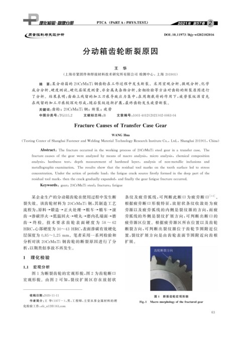
图 1 为断裂齿轮的宏观形貌, 图2 为齿轮断口
宏观形貌。由 图 2 可 知, 裂 纹 扩 展 区 存 在 放 射 状
图 1 断裂齿轮宏观形貌
收稿日期: 2020-11-11
作者简介: 王 华( 1977- ), 男, 工程师, 主要从事金属材料的理
Fi g 1 Macromor p holo gy ofthefracturedg ear
化检验工作, sfc _ n12@163.com
6 3